Need more information?
Get in touch with Paul Schreuders (CEO)
- +31503162888
- schreuders@xparvision.com
XPAR Vision is a firm believer that the current performance of the glass container industry has not reached its limit. Weight reduction, waste reduction and zero defects production are now possible by using the company’s equipment. In a series of exclusive articles for Glass Worldwide, Paul Schreuders shares the results of implementing the company’s technologies and how they help the glass industry.

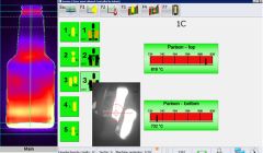
In part seven of this series, the capability of the XPAR Vision Blank side Temperature Control solution (figure 1) was explained. Multiple measurements within one cycle of both glass (parison) and metal (blanks, neck rings, plungers) are automatic and accurate in both time and position and therefore allowing for accurate and constant monitoring, without consuming operator time. In addition to its capability, possibilities for application (eg optimise swabbing) and potential advantages have been explained.
This article focuses more on accuracy of measurement and its relevance, specifically the accurancy of measurement of different types of sensors available in the market.
Every hot object emits infrared radiation that is dependent on the temperature of the object. A hotter object sends more radiation than a colder object. The working method of a contactless infrared sensor is based on this physical principle.
The sensor measures the amount of radiation. With some mathematics, the sensor can calculate the temperature of the object. In practice, it is a little more complex to determine the temperature, because objects of different materials with the same temperature do not emit the same amount infrared radiation. For example, cast iron of 500oC emits much less infrared radiation than a stone with the same temperature. But the story gets more complicated because for metals, for example, the amount of radiation is also highly dependent on the surface quality (shiny, rough or oxidised), so there is always an uncertain factor about the amount of radiation of an object.
This unknown factor is called the emissivity of a material. For metals, this factor is very sensitive to the surface of the metal. For example, a new mould has completely different emissivity than a used mould. By this unknown and ever-changing emissivity, an error of the temperature measurement is made. For commonly used infrared sensors, this temperature error can be more than 30o-50oC!
Every temperature change of a few degrees of the blank moulds influences the glass distribution of a bottle or jar. A constant variation of temperatures due to inaccuracy of measurements leads to continuous variation of the glass distribution of a bottle/jar. In order to ensure constant quality and repeatability, the temperature reading of moulds or plungers must be accurate within two degrees, otherwise one cannot use this temperature reading to adjust the cooling of blank moulds.
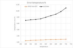
By choosing the right infrared sensor and a good calibration procedure, the error and dependency of the emissivity changes can be made very small. XPAR Vision’s Development Department has constructed an infrared sensor that is less sensitive to changes of metals emissivity. Figure 2 displays the error of measurement of the temperature. The red line is the error of a so-called micro bolometer sensor type. For metals, the micro bolo infrared sensor gives an expected error of 7%-10%. This means that the micro bolo sensor measures the temperature with an error of 30o-40o!
The infrared sensor used in the XPAR Vision BTC only has an error due to the change of emissivity of 0.5% or less. This means that operators can trust the readings of the BTC for every mould, old or new and use this temperature information to adjust the cooling of blank moulds.
Close accuracy is needed to gain an understanding of certain defects related to the temperature and process changes at the forming process on the blank side.
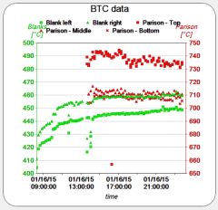
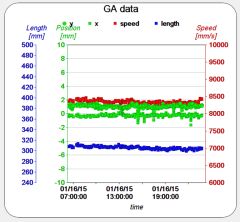
An example in practice is found in relation to a defect called ‘loading marks’. At a customer where the GA and BTC was installed, XPAR Vision has monitored both loading and temperature behaviour (figure 3).
According to the GA data, the speed, length and position of the gob was stable and at target. Nevertheless, ‘loading mark’ defects occurred and a blank was exchanged resulting in no defect. But after several hours again, the loading mark defect appeared and again, blanks were exchanged. This defect appeared on many cavities, with an interval of 12-36 hours. What could be the reason?
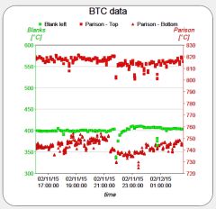
Monitoring the blanks, parison temperatures and using the IR-D data explained the root cause of the defect. The blank change also showed a glass distribution change; more glass in the bottom and less glas in the shoulder. In time, the distribution changed to the normal level (figures 4 and 5).

The surface of the parison is measured at three locations (neck, middle and top), while the blanks were measured at the settle wave level. After the exchange, a constant increase of the temperature of the blank was observed. Looking at the parison, a constant decrease of the skin temperature (just a few degrees) was noted.
This means that the heat transfer changes slowly in time. The temperature decrease of the parison is also in correlation with the intensity distribution change in time. The condition of coated blank changes in time; the coating wears out and contact between glass and blank increases, resulting in a higher blank temperature (about 10o). But when the coating is gone in the blank, there will be a higher friction level between the gob and blank, resulting in loading marks.
Another example showed thin necks due to poor loading, where the length of the gob is shorter (see figures 6 and 7). The neck temperature of the parison shows an increase of temperature until the IR-D starts to reject for thin neck. Just a 10o difference at the parison neck has a dramatic effect on the quality of the bottle.
As demonstrated within this article, accuracy and continuity of temperature measurements are of utmost importance for creating production with low process variation and for creating bottles/jars with low variation of glass distribution. As different measurement devices exist, it is important to choose the right one.
